4. Design
This section presents a BCR design strategy, including discussion of general design considerations, full-scale system scale-up, design components, outfall, hydraulics, materials, and site control. General submittal recommendations for design of BCR systems is also presented. The contaminants of concern may be removed aerobically or anaerobically (see Figure 2-2), but the focus in BCR design is on sulfide production in the anaerobic zone.
As noted in Section 3, inherent dangers exist in any cookbook design approach because the conditions on-site may lie outside the range of conditions that were originally used to develop the standardized design criteria. MIW problems present a wide range of possible conditions, and a specific site could fall outside the guidance provided here. Use professional judgment when considering whether the advice provided in this document is appropriate for a given particular site.
A wide range of technical knowledge (presented in Section 1 and the appendices) and skills are required to design a BCR. The design effort usually requires a team that includes capabilities in geochemistry, chemical analyses, engineering, hydraulics and hydrology, fieldwork, soils and foundations, construction estimation, and microbiology. Team members should communicate effectively.
The difference between equilibrium and kineticsThe study of rates of reaction. (rate) as described in Section 1.3 is another concern for design. Equilibrium usually predicts the formation of insoluble metal sulfides. Some metals, however, may be kinetically trapped by adsorptionNon-covalent bonding of a chemical to a solid surface. to natural organic matterStrictly defined, compounds in which carbon is bonded to hydrogen. Generally describes decomposed biological residues and other organic compounds synthesized by organisms. and therefore not able to react with sulfide. If the organic matter is colloidal, the attached metal flows through the system untreated. Thus equilibrium expectations can be violated due to kinetic rates. Some BCR systems have much higher initial effluent concentrations of total metals than the dissolved metal forms, and many believe that colloidal materials carry much of the metal found in a BCR effluent. Due to both equilibrium and kinetic realities, BCRs may not fully treat each metal in MIW or completely remove other constituents. In some cases BCRs can discharge elevated levels of other constituents such as sulfides, nutrients and organic material. This can be a concern particularly during the start-up phase of a BCR, but can also be a concern during operation of the BCR (see Section 4.2).
4.1 BCR Design Evolution
BCRs were originally inspired by natural wetlands and therefore were considered a form of constructed wetlandA man-made treatment system using saturated soils or sediment beneath standing water to remove contamination. Constructed wetlands almost always treat waste water of some type and almost always contain wetland plants.. Treatment wetlands are designed largely on areal loadingMass of something per time entering a volume (volumetric loading rate) or flowing into an area (areal loading rate). and residence time, and a similar design approach was initially used for wetland treatment of MIW. Kleinman (1986) suggested 5 m2 of wetland per L/min of mine drainage, a loading rate of 0.29 m3/m2-d. This value was subsequently revised to 15 m2 per L/min (0.096 m3/m2-d) (Girts et al. 1987).
In contrast to a hydraulic loading rateThe volume of water applied to a system per time., Brodie et al. (1988) proposed an area per mass loading of 0.75 m2 per mg Fe/min. Dietz et al. (1994) suggested a similar areal design on acidity, based on 6 g/d/m2. However, the failure of a single areal rate to describe the performance or design of a unit had become apparent. For example, Hedin and Nairn (1990) found no clear relationship between iron areal load and removal for three different wetlands.
The idea of a volumetric rate of sulfide production (or sulfate reductionThe stripping of oxygen atoms from sulfate (SO₄²⁻), most often yielding sulfide (S²⁻) as an ultimate product.) has also been put forward to describe BCR design; however the initial rate of sulfide production is in excess of the long term design rate. Recent design developments have incorporate the blending of effluent and influent water to utilize excess hydrogen sulfide and sequential use of the organic substrateEither (a) a chemical which reacts or (b) a solid surface or (c) an electron donor.. In this case, design should be based on a total sulfide production rate in mol/d greater than the expected total metal load in mol/d. McIntire and Edenborn (1990) reported rates comparable to coastal marine sediments, with 2.0 to 600 mmol S m-3d-1 measured at the Friendship Hill (PA) system (see Friendship Hill Case Study, ITRC Mining Waste Treatment Technology Selection) treating water with pH of around 3. Wildeman’s group at Colorado School of Mines similarly offered 300 mmol S m-3d-1 as a conservative estimate based on the Big Five wetland (Machemer et al. 1993). Lower values, however, have been reported; Mueller et al. (1996) determined sulfate removal rates of 128 to 547 mmol S m-3d-1. The studies at the Big Five tunnel also showed that permeability of the substrate was a critical design factor for successful constructed wetland operation.
The first published attempt to model geochemical and biogeochemical processes in a BCR seems to have been by Klusman around 1990 (Klusman et al. 1993). MINTEQA2 code was modified to calculate rates, including an assumed sulfide generation rate, and model plug flow by doing time steps on a batch case. Although capable of matching effluent concentrations from several operating wetlands (BCRs) to some degree, the authors noted that inadequate experimental data existed to confirm model results against wetland realities.
In addition to the question of design values, specifics of design have been the subject of doubts. Is the direction of flow better as vertical down, vertical up, or horizontal? Which redox condition, aerobic or anaerobic, results in better treatment? Are plants important? On the subject of flow direction and redox, Dietz and Stidinger (1996) studied paired surface-flow (horizontal flow with open water) and vertical flow (downflow) wetlands in series and parallel and found subsurface flow performance to be significantly better for alkalinity impact, acidity reduction, and iron and aluminum removal. Manganese and calcium were significantly higher in the vertical flow effluent, the latter presumably due to calcium carbonate dissolution related to acid neutralization. They speculated that vertical flow had improved contact between substrates (both mushroom compost and limestone gravel) and the impacted water. Although subsurface flow is now recognized as desirable for removal by sulfide precipitation, the direction of flow has not been shown to affect removal. That noted, most units are vertical downflow for simplicity.
The role of plants also came into question in the early 1990s. If removal was by sulfide precipitation and wetland plants aerate the subsurface, perhaps plants were not desirable. Not having plants would also decrease concerns over bioaccumulation. On the other hand, plants increase microbial counts in the subsurface and as the senescent mass decays, replenish the bed organic matter. As noted in Beining and Otte (1997), a natural wetland in Wicklow, Ireland, has treated MIW for more than a century and, based on plant growth, is calculated to continue treatment for at least another century. A powerful counter-example of the potential role of plants was the shallow Brewer Pad 5 system (see Appendix B.6 Brewer Gold Mine Case Study) operated from 1993 to 1995. When vegetation was present, the system was aerobic and copper removal efficiency was poor. A deeper unit would allow for increased anaerobic volume where the plant roots may not go. Although it is not clear whether plants are a net benefit, current BCR designs often exclude plants through placement of a geotextile cap, a thick gravel layer, or a free water surface with a depth of one meter.
4.2 BCR Design Considerations and Criteria
Following Figure 2-1 and the testing protocols in Section 3, the design team performs the following tasks prior to design:
- Characterize the MIW influent quality and flow.
- Characterize the site.
- Identify the treatment goal, including applicable rules and regulations.
- Consider and possibly select pretreatment, based on the material presented in Section 2.4.
- Estimate the amount of sulfate reduction sufficient to precipitate metals as sulfides.
- Perform bench-scale tests (Section 3.4) in the laboratory, on site, or both to determine:
- loading range, substrate thickness, and residence time
- substrate mixture
- substrate degradation rate
- metal removal efficiency (MRE)
- Perform pilot-scale testing at the site for an extended period, which establishes performance at the specified loading rate and with the specified substrate mixture.
-
Evaluate effluent quality for compliance with applicable discharge standards including water quality parameters such as nitrate/nitrite, ammonia, phosphorus, biological oxygen demand (BOD).
Given the determination of the various design variables and constraints as described above, the following subsections describe in greater detail some additional design considerations, including influent chemistry concerns, site conditions (including discussion of BCR covers), temperature effects, flow variability, and parallel treatment trains.
4.2.1 Influent Chemistry Concerns
Some characteristics and constituents of MIW can adversely affect BCR performance, so MIW pretreatment is usually necessary. For example, iron and aluminum both can produce sludges, which rapidly plug BCR pores. Specific pretreatment technologies are reviewed in Section 2.5 and more detail is available in ITRC MW-1 (ITRC 2010). In addition to the characteristics and constituents listed below, Appendix A. Physical, Chemical, and Biological Reactions in a Biochemical Reactor includes additional metals that are less common in MIW influent but still important.
4.2.1.1 Iron
As MIW is neutralized and increases in ORP occur, iron oxyhydroxides and hydroxysulfates form (see Appendix A.1.2). These solids are dense and deposit readily on surfaces. The solids also tend to form a large volume of fluffy flocs that can rapidly plug a porous bed. If the MIW is acidic and contains more than 100 mg/L (Reisman et al. 2008) of iron, then the passive treatment system design must consider pretreatment to remove iron. At lower concentrations, iron still can be challenging and pretreatment is advisable. The Pourbaix EhThe redox potential is the tendency of a compound to gain an electron. This is most often measured as the voltage required to prevent electrons to transfer between the measured sample and a standard reference electrode. For Eh, that standard reference, defined as zero volts, is H2 → 2 H+ + 2 e- at a specified standard condition.-pH diagram (Figure 1-2) shows that iron will almost always stay in solution below pH 2, and in highly reducedIn chemistry, having gained electrons. Often gaining electrons is accompanied with gaining protons (hydrogen). As an example, when O₂ reacts with H₂, the oxygen is reduced, forming H₂O. conditions remains as Fe2+ (aq) up to near-neutral pH. The decision tree in Figure 2-3 (link to Figure 2-3) shows that most often the pretreatment chosen in this case will be an open limestone channel (OLC) (Table 1-1) which raises both pH and Eh, causing iron oxyhydroxides to form, followed by a settling pond. In some cases a SAPSsuccessive alkalinity producing system/RAPSreducing alkalinity producing system may instead be used followed by aeration and settling or followed directly by the BCR unit.
As shown in Figure 2-3, an anoxic limestone drain (ALD; see ITRC MW-1 2010) is appropriate pretreatment for anoxic (dissolved oxygen (DO) less than 1 mg/L) MIW with modest amounts of ferric iron (Fe3+ less than 1 mg/L). After the ALDanoxic limestone drain adds alkalinity, the water should flow to a settling basin to allow the iron oxyhydroxides to settle.
4.2.1.2 Aluminum
Aluminum hydroxides are a favored floc form for removing colloids from drinking waters. Aluminum hydroxides tend to be gelatinous, sticky sludges, which can rapidly plug a BCR and thus if aluminum is present around or above 10 mg/L (Reisman et al. 2008), pretreatment for this metal must be considered. Because aluminum removal requires a higher pH and thus more alkalinity to remove than iron (Section 1.3), the pretreatment most often used is a SAPSsuccessive alkalinity producing systems. Unfortunately, the sludgeA watery semi-solid. is formed atop and within the SAPS, and periodic flushing or substrate replacement may be required.
4.2.1.3 Mercury
If mercury (Hg) is present, the potential formation of methylmercury in the system can be a concern due to the reducing conditionsA system in which the gain of electrons is energetically favored due to a low reduction potential.. Although sulfate reducing conditions can capture Hg, the reducing conditions also allow the formation of highly toxic and mobile methylmercury (King et al. 2002). Sulfate reducing bacteria (SRB) have also been shown to promote methylmercury formation. If total mercury is analyzed, the analysis does not measure methylmercury and the effluent may be more toxic than anticipated due to the methylmercury content. If mercury is present testing for methylmercury should be incorporated.
4.2.1.4 Potentially Inhibitory Constituents
BCRs rely on the activity of microorganisms. If contaminant levels become too high, the microbial culture may be adversely impacted, especially by low pH or high levels of zinc or copper (50 and 5 mg/L, respectively (Ruhs et al. 2006); see Section B.1.4). If the MIW has high zinc or copper concentrations, pretreatment improves BCR performance. Another method to reduce high zinc and copper concentrations for treatment is to simply dilute the influent to a BCR with recycled effluent or with other water low in the metals.
For low pH, pretreatment may be required. Both celluloseAn unbranched polymer of glucose found as the primary structural unit for green plants. degraders and SRBsulfate-reducing bacteria do not tolerate pH changes. Although SRB have been reported to thrive in acid conditions, these acid-tolerant SRB most likely are not the same organisms found in the manure used as a BCR component. Perhaps more importantly, cellulose degraders are believed to cease activity below pH 5 (Qu et al. 2005). The BCR influent therefore should not be too acidic (less than pH 4). The alkalinity in the BCR neutralizes pH to some extent, but also biological activity will affect pH. The formation of carbon dioxide from organics results in a shift in carbonate equilibrium, potentially lowering pH slightly as carbonic acid is formed. On the other hand, sulfate reduction results in sulfide, but the dominant species is likely to be HS-, thus raising pH. The effluent pH from BCRs is often above 6.0 (USEPA 2001).
4.2.1.5 Oxygen and Nitrate
Microbial metabolism of oxygen and nitrate yield more energy to microorganisms than does sulfate reduction. Since many BCR treatment processes involve sulfide generated by SRBsulfate-reducing bacterias, design of a BCR must consider oxygen and nitrate in the MIW that is treated by a BCR. If MIW contains oxygen and/or nitrate, an aerobic zone and nitrate-reducing zone must be maintained within the BCR. In this anoxic zone, nitrate consumes the refractory BOD and soluble organic substrate. Nitrate is reduced to nitrogen gas by denitrifying bacteria and consumes acidity. Nitrate treatment likely improves water quality although it also decreases BCR efficiency in terms of sulfate reduction and sulfide generation. A portion of the organic in the substrate is used for nitrate reduction, and thus the sulfate reduction rate is decreased and the BCR consumes more substrate per time increment. Rather than pretreatment, the testing phase described in Section 1.3 should include characterization of the anoxic layer depth by Eh and estimate the rate of depletion of organics due to oxygen and nitrate reduction (that is, increasing the BCR electron donorThe molecule which is oxidized during metabolism. For example, one glucose molecule used as an electron donor can result, with the addition of six water molecules during metabolic reactions, in six carbon dioxide molecules, 24 protons (H+), and 24 electrons (e-). demand). The presence of oxygen or nitrate in the MIW may require additional media depth and volume in the BCR to maintain a comparable design sulfate reduction and sulfide generation design criteria.
4.2.2 Design for Site Conditions
Siting a BCR system depends primarily on the location of the source of MIW to treat. Most BCRs are located in remote, hard-to-access areas close to the source of the MIW. These settings are often also in steep terrain, which dictates the area available for the BCR; some BCR systems snake down a hillside like the switchbacks of a mountain road. Private land may abut the location, so consider the value of land purchase in site planning. Be creative when considering placement of a treatment system in steep and challenging terrain, and remember that construction may require added flat space. Maintenance personnel must have access to the site as well.
When the terrain is challenging, one design alternative is to pipe the MIW a significant distance to a more suitable and accessible location. An advantage of steep terrain is that often the elevation difference between the location of the MIW and the BCR system allows gravity flow to feed the MIW through the BCR other treatment units, and to the receiving water.
In addition to topography, factors to consider while siting a BCR system include local precipitation, vegetation, type of soil at the water source and at the BCR system site, availability of materials and resources needed to build the BCR system, and neighbors. This guide does not address soil mechanics or the design of foundations, but the design team must also consider these issues. The availability of utilities during construction and operation is another site-related issue that must be considered if energy is required. If electricity is unavailable, solar or wind power and battery storage is a proven option for operating remote systems.
The site specific and general topography of the mine area should be evaluated during the siting of the location. Address the following questions regarding the mine area:
- Where will the MIW be captured and conveyed to the BCR system?
- Where will the BCR be located?
- Where will posttreatment units such as aerobic polishing cells (APCs) and final discharge (outfall) effluent be located
- How will equipment get to the site?
Establishing a good relationship with the local populace, if present, is important because happy neighbors are more likely to report observed problems at the site, and are less likely to protest. If present, the neighbors should be contacted early in the process and inform them of the reason for the proposed system, the expected construction issues and duration, the finished appearance, and frequency and magnitude of maintenance visits. BCRs treating large sulfate loads have the capacity to off gas low levels of hydrogen sulfide. Hydrogen sulfide odors can be intensely unpleasant and the human sense of smell becomes rapidly fatigued by exposure to these odors. Hydrogen sulfide is hazardous at low concentrations National Institute for Occupational Safety and Health-Recommended Exposure Limits (NIOSH REL) is 10 ppm for 10 minutes. If the site can generate significant hydrogen sulfide emissions, then site control is required and a provision for an odor control system such as oxidation, aeration, and biofilters should be included in the BCR design.
Because most MIW is found at active, abandoned, or reclaimed/closed mines, hazardous materials may also be present both above and below ground at a site, including below ground surface. The design should include controls for all known or suspected contaminants that workers may be exposed to during construction and maintenance of the BCR. One such control is to create an on-site repository or to find an off-site location to accept contaminated materials.
BCRs located in cold weather environments may need to be protected from freezing conditions. If the MIW chemistry allows (it has virtually no dissolved iron, aluminum, or suspended solids), then the BCR can be fed from the bottom, similar to a fenFens are peat-forming wetlands that receive nutrients from sources other than precipitation, usually from upslope sources through drainage from surrounding mineral soils and from groundwater movement. Fens differ from bogs because they are less acidic and have higher nutrient levels. They are therefore able to support a much more diverse plant and animal community. These systems are often covered by grasses, sedges, rushes, and wildflowers. Some fens are characterized by parallel ridges of vegetation separated by less productive hollows. The ridges of these patterned fens form perpendicular to the downslope direction of water movement. Over time, peat may build up and separate the fen from its groundwater supply. When this happens, the fen receives fewer nutrients and may become a bog. See EPA website: http://water.epa.gov/type/wetlands/fen.cfm. Otherwise, the BCR could be buried. Some examples of buried BCRs can be found in the case studies:
- B.4 Ferris-Haggerty Mine Case Study (second pilot), Wyoming
- B.5 Fran Coal Mine Case Study, Pennsylvania (Gusek and Schueck 2004)
- B.9 Wheal Jane Mine Case Study, Cornwall, UK
BCR cover designs (downflow units) should consider the following:
- What is the frost depth or expected snow cover at the site?
- To minimize the geotechnical surcharge loading (and consolidation/compression) of the substrate, the cover fill material should be as light as possible. Wood chips have been used in this capacity, but see item 5 below.
- For acidic MIW with dissolved iron and aluminum, the cover design should allow a zone of free standing water immediately above the substrate. This practice avoids the need for perforated pipes (which can plug) on top of the substrate.
- If a high permeability zone of lightweight material is to be in direct contact with substrate, there should be limited suspended solids allowed in the BCR influent and the lightweight fill material should be inert with respect to altering the MIW influent chemistry (for example, limiting the possibility for precipitation reactions to occur).
- If a high permeability zone of light weight organic material (such as wood chips) is in direct contact with substrate, any alternations in MIW chemistry should not cause precipitation of solids that could cause plugging.
- Any geomembrane or geotextile materials used in the cover design should be covered with a soil layer that can be revegetated with native grasses.
- Covers should include dedicated ports for sampling the substrate over time.

Figure 4-1. Schematic cross section of a cover design.
To develop a zone of free standing water, the septic system infiltration chambers or similar units can be placed directly atop the substrate and covered with lightweight fill. These chambers are usually made of plastic or concrete. If the MIW is very acidic, plastic chambers should be specified, because concrete chambers are subject to corrosive attack.
The cover design engineer should assess the need to include geomembrane or geotextile layers in the BCR cover. This determination is based on the climate and the grain size distributions of the various materials in the cover. These materials may be segmented in a way that allows their preservation, salvage, and re-use when the substrate is periodically exhumed and replaced.
The inclusion of a cover restricts BCR inspection and sampling of substrate materials for long-term consumption and degradation (see Section 6). Consequently, multiple sampling ports for collecting substrate materials should be included in the cover design. Some designers have included five “nests” of sampling ports in a square BCR as shown in Figure 4-2.
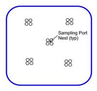
Figure 4-2. Schematic of five nest sampling ports in a square BCR.
If the surcharge load on the substrate is a concern, geotechnical testing should be conducted to evaluate how the substrate behaves in response to the extra weight. As the substrate ages, its ability to support the cover load may decrease and the cover surface may subside. Assuming uniform substrate degradation or consumption, the thinner zones of the substrate (around the perimeter of the BCR) may subside less than the center and the cover may lose its ability to shed rainfall or runoff. The project engineer should consider these differential settlement amounts in the cover design to minimize this effect.
4.2.3 Temperature Effects
Bench- and pilot-scale systems are more susceptible to ambient air temperatures than full-scale in-ground systems. The temperature in the test systems varies more and extends lower and higher than it does in the full-scale units. The effects of temperature on biological activity are also unpredictable. Although the biological rule of thumb is a doubling of activity for every 10°C, increase in temperature in the range 4 to 40°C, some systems have given higher volumetric rates of sulfate reduction as temperatures lowered (for instance, see Appendix B.4 Ferris-Haggerty Mine Case Study).
If the influent water is especially cold (less than 10°C), then it may be beneficial to incubate (during start-up) the BCR at higher temperatures (greater than 10°C, but less than 20°C) to mature the microbial population (see Ferris-Haggerty).
BCRs and their component parts can freeze, especially since mines are frequently located at high elevation. Heat lost from the water is equal to the heat gained by the air, assuming little heat transfer to the soil. The heat balance in a BCR is thus analogous to that for ponds:
Q(Tin – T) = hA(T – Tair)
where:
Q = flow rate, m3/s
Tin = influent water temperature (often the same as local groundwater) °C
T = mean temperature in the BCR °C
A = area exposed to air (footprint) m2
h = heat transfer coefficient (m/s)
Although a value of k for open water (and measured in areas with minimal snowfall) has been reported (Mancini and Barnhart 1968), this equation may not be useful for most mine waters because of the low temperatures that occur at mining sites. For a given location’s lowest sustained temperature (Tair), if T solves to zero or lower, an insulating layer of ice will form. The ice (and snow) insulation thus changes the value of k so that it decreases heat loss to the atmosphere and the value of k given above no longer applies.
4.2.4 Flow variability
As emphasized in Section 2 and during the testing process described in Section 3, the MIW flow characteristics should be observed over several seasons. To account for variability in flow, equalization and storage volume may be required. The design of such storage systems is described in numerous textbooks, but for MIWs, the designer should especially consider corrosivity and possible sludge generation during storage. The BCR must be designed to accommodate the highest hydraulic load, but also must include capacity to safely discharge overflow.
The preliminary data collected should include not only flow rates but also precipitation. The design team should analyze this data for correlations, because in many instances the volume of water to treat is directly related to the local precipitation of the area (with some delay period). In this case, prevention is preferable to treatment, and diverting stormwater away from the former mining site results in a smaller volume of water to treat. If a strong correlation between rain events and flow rates exists, the design may focus on decreasing the permeability of the collection area, increasing evapotranspiration, channeling storm water, and creating detention basins if required. In other cases, the former mining sites are influenced by not only the local precipitation, but also by groundwater that finds its way to the mining site. In this latter case, extensive investigation of groundwater flow to intercept sources may be futile.
4.2.5 Parallel treatment trains
If a unit requires maintenance, where will the flow go during this work? For some processes such as an aeration pond, maintenance might be done while flow continues. For example, precipitated iron can be dredged out under normal flow conditions. On the other hand, when a BCR has exhausted the organic or alkalinity source, the BCR volume must be replaced. In most water treatment systems, parallel units are included to allow for such maintenance. It is similarly preferable that BCR systems be built with parallel units and piping to allow any given unit to be taken offline as needed.
4.2.6 Full-scale systems
Upon completion of the field pilot test, full-scale design should take into consideration seasonal fluctuations in flow rate and in the chemical composition that may not have occurred during a pilot scale test if it was conducted for a short time. Fluctuations in loading can be managed using equalization ponds, flow bypass, recirculation or other pretreatments.
The field pilot-scale test provides data for scale-up. In some cases that scale-up is simply an application of the rates found at pilot-scale. For example, biology and MIW chemistry occur at micro-scale or smaller, therefore scale-up might be thought of as simply applying areal and volumetric rates from the smaller-scale tests to the total flow and load that require treatment. Scale-up, however, can both positively and negatively affect other issues.
On the positive side of increasing scale is the diminishing impact of edge effects. Edges promote heat transfer and also are frequent locations for short-circuiting. As the volume of a system increases, the fraction of volume exposed to surfaces decreases, therefore temperature variation due to ambient air contact declines and the fraction of edge-influenced, short-circuiting flow (along walls) also decreases. On the negative side, the availability of materials can be a problem, and construction of systems with unusual or rare materials at full-scale can be a challenge.
4.3 BCR Design Components
While BCRs are the focus of this design guidance, the information presented in this section applies not just to BCRs but also to related systems termed anaerobic wetlands, sulfate-reducing bioreactors, and permeable reactive barriers when these systems are designed to produce sulfide by the reduction of sulfate through biological means. This process is not the sole form of metals removal observed in BCRs. Metals are removed by precipitation as sulfides and adsorption to organic and inorganic ligands (including ion exchange), but in some cases also may be removed by precipitation as oxides or carbonates. In addition to metals removal, acidity may be neutralized both as sulfate reduction consumes protons and produces hydrogen sulfide and more importantly by carbonates, most often limestone, in the substrate that dissolves and provides alkalinity (see Section 1.3).
4.3.1 Flow direction
A BCR is unlikely to benefit from surface flow. Exposing the MIW to air as surface water will increase the oxygen load into the reactor, resulting in the consumption of organic matter to decrease DOdissolved oxygen rather than as a source of electron donation for SRBsulfate-reducing bacteria. Instead, the influent to a BCR is best distributed through a highly porous lens such as a layer of large gravel. The high hydraulic conductivity of gravel as compared to BCR substrate (10 cm/s compared to 0.001 cm/s) will give good distribution of the fluid to the substrate (although see discussion of influent distribution in Section 4.4.2.2), and the stagnant air in the pore space of the gravel layer greatly reduces oxygen transport rates from the air.
Although subsurface flow is preferable in a BCR to surface flow, the direction of flow, whether downflow, upflow, or horizontal flow (as shown in Figure 4-3) has not been shown to affect removal (Section 4.1). The biology and chemistry occurs at a scale where gravitational direction is unimportant. Hydraulics are, however, important and differ significantly between the flow directions. Vertical flow systems are generally downflow because an upflow system is more prone to plugging due to solids in the influent water. Compared to horizontal flow, vertical flow gives a greater allowance for headA specific measurement of water pressure above a geodetic datum. It is usually measured as a water surface elevation expressed in units of length. loss. In a horizontal flow system, excessive head loss will result in overland flow, bypassing treatment. On the other hand, the maintenance of horizontal flow systems may be easier than for vertical flow systems, because the location of a short circuit can be accessed. In a vertical flow system, localized failure may be hidden under the distribution layer.

|
|

|
|

|
Figure 4-3. BCR bed configuration for (a) vertical flow and (b) horizontal flow.
Source: Dr. Mark Fitch, Missouri University of Science and Technology
Another consideration for flow direction is oxygen supply. Horizontal flow allows for oxygen to contact the media, and thus presumably more oxygen fluxThe mass (mass flux) or volume (flux) moving through an area per time. comes into the media. Added oxygen flux may shorten the lifespan of the reactor because the organic is more rapidly consumed, but may also result in more small carbon for use by SRBsulfate-reducing bacterias and thus result in a higher rate of sulfate reduction. At present, no studies have compared the flow configurations to demonstrate whether organic degradation rates differ (Deitz and Stidinger 1996).
4.3.2 Media Design
Section 3 describes the substrate selection process and subsequent testing. The media used in a solid substrate BCR should be designed and evaluated with six objectives in mind (see Table 3-1):
- Long-term organic source. The media should provide sufficient BOD to both deplete any influent oxygen and to maintain a sufficient rate of sulfide generation.
- Short-term organic source. The media should have enough readily degradable organic material to allow the system to quickly become anaerobic and create sufficiently reduced conditions that favor SRBsulfate-reducing bacterias.
- Organism source. The media should have seed organisms or be seeded with a known culture of organisms to establish anaerobic conditions, cellulose degradation, and sulfate reducers. Batch studies of inocula have shown that media from existing BCRs give a shorter period to produce sulfate reduction and the appearance of H₂S and a somewhat higher rate of sulfate reduction over several weeks than dairy manure (Pereyra et al. 2008). Often there are lagoons or slime dams at mine sites; the sediment from these sites can be used as an inoculum for the reactor (Mary Deflaun, Geosyntec personal communication). A combination of both aerobic and anaerobic inoculum works best since oxygen and nitrate in the influent must be consumed before the anaerobic processes commence. Often, a good inoculum for a full scale BCR is the media from a pilot scale unit operated at the same site.
- Alkalinity source. A BCR may require an alkalinity source because most MIW is acidic, and biochemistry cannot easily increase pH. Alkalinity addition may not be needed for neutral or alkaline MIW. However, additional alkalinity can suppress fermentation bacteria in short-term electron donor materials during start-up. This alkalinity may also protect the pH-sensitive bacterial community during short-lived acidity upset conditions.
- Bulk for hydraulic conductivity. If the bed is impermeable, no water will flow through it.
-
Attachment sites for organisms. Most organisms live in small biofilm communities attached to surfaces, which are provided by the solids in the media.
Typically, 10-30% by weight limestone gravel is included in the substrate blend to provide a source of alkalinity and bulk. The long-term organic substrate of choice is often wood. The preferred wood particle size is currently an unresolved question. Smaller wood particles increase the rate of soluble organic evolution due to a greater surface area, while larger wood particles last longer and maintain lower concentrations of soluble organics in the BCR. Combinations of larger wood chips and smaller sawdust materials in a BCR may provide both these long and short-term benefits.
The concentration of soluble organics in BCRs is thus a balance of the competing needs of longevity (large pieces) and surface area (small pieces) relative to the rate of decomposition of the wood particles. Characterization of several BCR organic substrates was offered by Seyler et al. (2003). Most wood has very little rapidly degradable material for consuming influent oxygen and creating initial anaerobic conditions. Thus, wood-based BCR substrates may benefit from admixtures (Section 2.8 and Section 3.1) such as unusual solid-phase amendments or liquid substrates (e.g. chitin). Chitin is a solid-phase substrate for use as a BCR media component is material made from crustacean shells, which contain chitin. Chitin is an aminated glucose polymer with small calcium carbonate particles. The crustacean shell has a chemical composition of approximately 20% chitin, 40% chitin-bound calcium carbonate, 30% protein, and less than 9% nitrogen (Venot et al. 2008). This material is a long-term source of organic substrate and provides alkalinity through calcium carbonate dissolution. Manure can also be added to a BCR to supply a culture of organisms for start-up and a short-term soluble organic source.
If there is an available source of liquid substrate, the system is accessible to refill the liquid substrate, and the system can be monitored regularly (weekly to monthly) for flow rate adjustments, then a liquid substrate reactor may be considered for long term sustainability, particularly if space is limited. In this type of BCR, the media might simply be gravel or local trap rock with an initial inoculum of organisms. A thin layer of manure is often used at the bottom of the BCR to provide the inoculum. The liquid organic feed rate should be adjusted according to flow and chemistry. A liquid base such as 25% sodium hydroxide can also be used to control pH and increase activity (Leviathan Case Study, Appendix B.8).
After the media has been tested at pilot-scale, the design of the BCR is relatively straightforward. If not done during the testing phase, the substrate materials should undergo comprehensive testing for incidental contaminants that could be introduced into the system. The pilot-scale unit allows determination of a sulfate reduction rate, and this value is then used to find the total media volume required (see Section 4.4.2). Where a sulfate reduction rate can be derived or assumed from similar sites a sulfate reduction rate may not be derived through testing. in this case the hydraulic Residence time will assume a default Sulfate reduction rated and the BCR designed accordingly (see Section 4.4.2).
Each unit of the passive treatment system is designed for an expected load of water, acid, and metal. The influent may be subject to high variability in load, particularly on a seasonal basis such as due to snowmelt. Design the influent capture system to provide loading control for variations from the expected loads. Excessive loading can affect different units:
- Excessive acidity can overwhelm alkalinity production and as a result inhibit sulfide production in a BCR. SRBsulfate-reducing bacteria are generally sensitive to decreased pH. The system described in Appendix B.9 Wheal Jane Mine Case Study is one such example.
- Excessive flow can scour solids from any unit, but is particularly troublesome when it occurs in sedimentationThe process of depositing entrained particles from water. ponds and APCaerobic polishing cell units.
- Excessive water velocity through biological processes can cause washout, which is the loss of biomass. The result is a steep decline or total loss of activity.
- Excessive flow also can promote short-circuiting in BCRs. The increased head pushes more flow through an area of higher hydraulic conductivity and the resulting higher velocity scours more material, thus decreasing conductivity further until a channel is formed.
- Excessive iron or aluminum can escape aerobic conditions and instead oxidize and precipitate in the anaerobic zone or compete for sulfide and thus decrease efficiency for other metals.
Loading control ideally means that a storage system is included to allow processing of all the influent MIW or that the system was designed in anticipation of variable loading. In the event of extreme variability, however, it might be necessary to (a) only partially treat all of the MIW water, such as processing through an ALDanoxic limestone drain pretreatment but bypassing some of the MIW around the BCR, or (b) treat only a part of the water and bypass the remainder past the entire sequential treatment system. Mixing of bypass water with treated effluent from the BCR may be considered. The designer must analyze the required cost and construction of storage capacity compared to increased treatment capacity. Bypass of water is generally a poor option, since protecting the receiving body of water is the goal of the system and in some cases untreated bypass water may not meet expected permit conditions
If the increase in load is due not to increased flow but rather to changes in concentrations, then the system should be designed for that higher concentration. The system is thus over-designed for typical values but is able to treat the maximum. Otherwise an influent control system with instrumentation and a programmable logic controller (PLC) could be used to shift flows. For example, a decrease in pH could result in a PLC opening a valve for additional alkalinity input through an on-demand active system.
4.3.3 BCR Sizing and Media Depth
The volume of a BCR and the quantity of the media within a BCR is established by considering the chemical reaction kinetics and hydraulics conditions that are expected. Reaction kinetics that may be considered include: a sulfide generation rate, the rate of removal of metals and/or the yield of dissolved organic carbon from cellulose degradation. Typically the slowest chemical reactions control the BCR size. Hydraulic conditions that are expected should consider the nominal and peak flows and the duration and frequency of peak flows. Reaction kinetics and hydraulic conditions are typically compared by calculating the residence time, or empty bed contact time, within the BCR. Professional judgment and experience are then used to establish a safety factor on the minimum design volume and media quantity established from analysis of reaction kinetics and hydraulic conditions.
An example of how to size a BCR using the observed sulfide production rate and influent metals loading to the BCR is provided in Appendix C (Example 4-1). An allowance, or safety factor, for media aging is included that accounts for reduced sulfide production rate over time and design flow rate. Although the literature reports a range of sulfate reduction rates, generally the range of 100 – 300 mmol/m3-d has typically been used for pilot BCR design.
It is important to account for the dynamic BCR behavior over time. The rate of decomposition of organic matter within the BCR media changes over time leading to changes in the microbial activity within the BCR over time. For example, the rate of sulfate reduction (sulfide production) will typically increase over time during BCR start-up. As the microbial population density within the BCR zones (oxic, transition and sulfate reducing) increases the rate of production of bioavailable organic carbon and sulfide often increases. As the readily degradable fraction of the media is depleted and microbial cellulose degradation provided a larger fraction of bioavailable carbon (electron donor) for sulfate reduction and sulfide production.
Pulles et al. (2001) showed that in the early operational days of a bioreactor there is a large loss of both microbes and organic carbon as it is flushed from the system. This was also noted by Glombitza (2001) and others. This initial period of high cellAn individual unit in a treatment system. yield and loss of organic carbon will be followed by a period of slower kinetics driven by use of cellulosic material that is eventually exhausted. Possible approaches to address these issues include recirculating BCR effluent during start-up and providing supplemental carbon if sulfate reduction rates decrease below design levels.
The design approach presented above assumes that metal removal is the primary purpose of the BCR and that complete removal of sulfate or nutrients is not a design objective. In the case that sulfate or nutrient removal is required to meet discharge requirements, the residence time of the BCT may by driven by reactions beyond sulfide production. Additional design considerations may results such as removal of excess sulfide or methane. Direct scaling of sulfide production rates beyond the range of 100 – 300 mmol/m3-d may be inappropriate because in general the rate of biological processes decrease in rate as the concentration of the limiting reactant decreases (bioavailable carbon or sulfate). In this, twice the BCR volume may not double the removal of a particular constituent of interest.
Similarly, the designed is cautioned against changing the depth of a full-scale BCR as compared to a pilot system. The maximum media depth is a function of the compressibility of the media. Under totally saturated conditions media compression may be mitigated and become negligible due to material buoyancy. For some media, compression may reduce the hydraulic conductivity of the bed when the bed depth is greater than one meter. Media bed depths greater than a meter should be evaluated using geotechnical principals. A maximum media bed depth of roughly 2 meters is advised unless the media is dominated by inorganic, large particles. For example, a limestone bed is expected to have minimal compression as compared to a manure/straw bed.
The hydraulic design of a BCR is illustrated in Example 4-2, Appendix C. Since the depth of a solid substrate BCR is limited by compressibility of organic media, the surface area of the BCR increases with increasing flow rate. In some cases, the peak seasonal flow may lead to lower hydraulic residence timeThe mean length of time a fluid element is in the volume of interest, usually determined by dividing the flow rate into the liquid volume. than required for complete treatment of all MIW constituents and nutrients. The maximum surface area of the BCR may be limited by the area of land area available at the site. In some cases, this may lead to selection of a liquid substrate BCR over a solid substrate BCR or a seasonal hybrid design. Example 4-2 in Appendix C illustrates linkage of hydraulic calculations and media volume estimates.
4.3.4 Sampling Points Within a BCR Substrate
Sampling ports could be incorporated into the design to allow for monitoring conditions along the depth (flow path) of the BCR (see Section 6.3.1). Sampling ports could be provided by embedding plastic pipe of appropriate size in various locations and at various recorded depths within the BCR bed. An example of such a sampler is shown in Figure 4-4. In some cases, socks of media contained in plastic net are placed in samplers to allow for withdrawal of substrate samples as the media ages and assay of organic depletion rates.

Figure 4-4. Sampling pipe/piezometer. Note perforations to provide pore water samples, removable cap, and wooden cone for driving into substrate.
Source: Dr. Mark Fitch, Missouri University of Science and Technology.
Sampling points should not be placed near one another because the pipe may act as a surface to allow for some short circuiting and because placing substrate between co-located pipes may result in voids. Although samplers with conical ends as shown in Figure 4-4 have been driven into BCRs after construction, this practice likely causes the opposite problem: compaction around and beneath the sampler.
4.3.5 Aerobic Polishing Cell
Many BCR installations include an APCaerobic polishing cell as a final element. An APCaerobic polishing cell is a shallow pond that aerates the treated water, allows some degradation of organic matter escaping the BCR, and also retains suspended solids (see Section 2.5). If manganese removal is a treatment goal, a limestone or other carbonate rock bed can be included in the APCaerobic polishing cell (see A.1.4 Manganese); however, the resulting pH may be 8 or greater. Often APCaerobic polishing cells are shallow enough that plant growth will occur and thus these APCs can also be considered aerobic wetlands. Plant uptake may help to remove trace metals. In conjunction with proper sedimentation processes, the APC can produce a final effluent water quality that is acceptable for discharge to receiving streams or other water bodies.
Butler et al. (2011) tested BCR effluent from four different systems for aquatic toxicity using USEPA's whole effluent toxicity (WET)Aggregate toxic effect to aquatic organisms from all pollutants contained in a facilities wastewater (EPA, http://water.epa.gov/scitech/methods/cwa/wet/) tests. The effluent was toxic, but further aeration removed toxicity for some samples. Aeration of the effluent removes dissolved sulfides and increases the DOdissolved oxygen content prior to ultimate discharge. If the BCR discharges over a weir with a few feet of drop, such aeration and concomitant toxicity reduction is likely to result. If WET testing standards must be met, additional bench testing may be necessary.
4.3.6 Outfall
The outfall is usually the point of compliance at which water quality monitoring is required as discussed in Section 6.2. Depending upon the regulatory discussion and expected operating permit, an outlet monitoring structure such as a small, automated sampler and some instrumentation might be required.
4.4 Hydraulics
The application of hydraulics and hydrology is a crucial element of BCR design. Water flows downhill, and the design of the system must anticipate that sometimes downhill in terms of the energy grade line is not literally downhill. Consider these three major aspects of hydraulics in system design:
-
The energy and hydraulic grade line (HGL) should be calculated for the entire system (BCR and pre- and posttreatment processes), and in so doing each unit of the system must be considered in terms of head loss. This approach should include an initial rough estimate and a later check of calculated values when units have been sized, with production of a process flow drawing including the energy grade line (EGL)A line that represent the elevation of energy head (feet/meters) of water flowing in a pipe, conduit, or channel. The line is drawn above the hydraulic grade line (gradient) a distance equal to the velocity head of the water flowing at each section or point along the pipe of channel (Sacramento State Office of Water, http://www.owp.csus.edu/glossary/energy-grade-line.php). and HGLhydraulic grade line.
-
The BCR bed is a heterogeneous porous media, which changes with time due to deposition, filtration, scour, development of biofilms, and chemical reactions. The flow path within the bed, should be calculated and allow for both changes in hydraulic conductivity over time within the bed and changes in the amount of short-circuiting.
-
The system is subject to variation in influent flow rate, such as from precipitation events or snow melt. Provisions should be made for handling stormwater and snow melt flows, which are likely as both sheet flow into the BCR and variations in MIW flow rates.
4.4.1 Sequential Treatment Hydraulics
Early in the design process, the hydraulic profile of the discharged and treated MIW should be estimated. Presumably the MIW emerges at the surface at some elevation, and the receiving body of water is at a lower elevation. Flow through a BCR and any associated pre- or posttreatment will result in head loss. The head losses for each element of the system should be estimated, including piping and flow control and measurement structures. Estimated head loss from the source to the receiving body of water can be plotted as shown in Figure 4-5.

Figure 4-5. Example of initial system hydraulic profile.
Source: Dr. Mark Fitch, Missouri University of Science and Technology.
The purpose of this initial profile is to show whether there is a clear hydraulic issue requiring a pump to increase head or, in the case of excess energy, dissipation of energy to prevent erosion. This first analysis is not a detailed engineering design, but rather a back-of-envelope estimate.
After the various units have been designed, perform a detailed analysis of friction losses, and plot the EGLenergy grade line and HGLhydraulic grade line against the flow pathway. Determine or check sidewall depths of open units from these grade lines. Compare overflow levels to the expected water depth. In most cases the expected weir depth of the BCR outflow structure is determined from the calculated head loss through the BCR subtracted from the EGLenergy grade line at the BCR inlet.
In determining EGLenergy grade line and HGLhydraulic grade line, consider not just the maximal value flows, but also the average and minimum expected flow rates. The system should be designed to accommodate the highest flow, but generally run at an average flow. In some cases, the BCR freeboard is designed to allow for storage of excess water, where outlet flow is determined for the bed at the expected water level and accumulation is the difference between inlet and outlet flows during the time of excess flow multiplied by that time. The rising water level (head) results in increased effluent flow. As the head increases and therefore flow increases, the metals and acid load to the bed also increases and the velocity in the bed is more likely to scour out organisms and deposited metals. Both increased loading and scour can result in BCR failure. At minimum flow rates, undesired deposition might occur in piping and channels, and the head losses through most beds decrease, which might require adjustment to the height of weirs to prevent water level decline exposing portions of reactors to oxygen.
4.4.2 Unit Hydraulics
The BCR and associated units may be thought of as having four possible governing hydraulic processes:
- Head loss due to flow through porous media, usually characterized by Darcy’s lawAn equation which relates flow through a porous material to the driving force and the permeability of that material.. In addition to the BCR unit, examples are ALDsanoxic limestone drain, open limestone drains (OLDs), RAPs, SAPs, and wetlands.
- Open basins in which the water hydraulic grade line will be equal to the elevation of the outlet weir or other control structure. Examples are aerobic wetlands, settling basins/clarifiers/sedimentation ponds, individual sub-basins within a cascade system, and aeration ponds.
- Head loss due to friction in pipes and channels, usually determined by Darcy-Weisbach, Hazen-Williams, or the Manning equations. Note that OLDsopen limestone drains and ALDsanoxic limestone drain appear to be channels but should not be analyzed as simple open channel flow due to the porous fill.
- Energy gain from mechanical input. Generally mechanized input is from pumps, but can also potentially come from pressurized air such as in jet aeration.
The decrease in head along the path of flow, dh/dL, is the hydraulic gradient in the direction of flow. For the entire system, this value integrates to the head loss, Δh, divided by the flow length, L. Most often the hydraulic gradient is approximated as this system difference, dh/dL = Δh/L. If the hydraulic conductivity of the homogeneous porous material is known, the flow rate may be calculated, or for a desired flow rate, the necessary head can be determined.
Although the term permeability is sometimes used interchangeably with hydraulic conductivity, the two are related as:
K = k g ρ/μ
where:
k = permeability, m2
g = gravitational acceleration, 9.8 m/s2
ρ = density of the fluid, which for water at room temperature is approximately 1000 kg/m3
μ = dynamic viscosity of the fluid, which for water at room temperature is approximately 0.009 P = 0.009 g/cm/s = 0.0009 kg/m/s
Measuring permeability in an operating BCR needs to be approached with an understanding that the value observed can be biased by several factors, the most important of which is the tendency of substrate to generate various gases such as carbon dioxide and hydrogen sulfide. True permeability or “saturated hydraulic conductivity” is predicated on a fully saturated test sample. The likely presence of gas bubbles in BCR substrate makes this measurement virtually impossible, so any permeability values derived from the static head elevation difference between the standing water on top of the cell and the outfall should be termed “apparent permeability”.
To be even more precise in this calculation of apparent permeability of substrate,consider the following:
- the friction losses in the pipes and fittings and the gravel bed (i.e., the drainage layer) that is typically placed on the floor of the BCR, beneath the substrate
- heterogeneity of the substrate itself
- the tendency of evolved gas bubbles to create preferential vertical pathways as the bubbles migrate to the surface of the substrate
- potential “dead spots” around the perimeter of the BCR
- seasonal variations in flow rate, temperature, and associated microbial activity that could affect the kinetics of gas evolution
Thus, even measuring “apparent” BCR substrate permeability should be considered an inexact science and values derived need to be considered in the context of the operating conditions.
The hydraulic loading, Q/A, is also the flux, q, and may be termed the Darcy velocity; for a downflow BCR, this is the surface loading applied to the BCR, where Q is the flow and A is the area footprint of the BCR. The Darcy velocity is also the apparent velocity of water through the porous material ignoring that the material is porous. The actual velocity of the water in the pores is
v = q/η
where:
v = velocity, m/s
q = flux or Darcy velocity = Q/A, m/s
η= porosity, dimensionless
For a BCR, apply the above equations generally to determine the relationship between flow and head. Darcy’s law can be used to determine head loss through the substrate, flow rate through the substrate, and residence time in the substrate. Head loss is simply Δh as determined for the given substrate hydraulic conductivity (K) and length (L) at the specified flow rate (Q) through the area of flow (A). Similarly, the flow rate can be found for a given applied or constant head. The hydraulic residence time (HRT) is slightly more complex. Hydraulic residence time is the mean length of time a fluid element is in the volume of interest (the BCR), and often is defined as:
HRT = Vη /Q (= ALη/Q = L η/q = L/v)
where:
HRT = hydraulic residence time, s
Because estimating the porosity of a system is difficult, in many cases the empty bed contact time (EBCT) is used instead of the hydraulic residence time.
EBCT = V/Q (= AL/Q = L/q)
where:
V = volume
In addition to accounting for head losses, certain hydraulic structures should be considered:
- influent capture
- influent distribution
- weirs
- overflow structures and loading control
- pipes and cleanouts
Each of these structures is discussed briefly in the following sections.
4.4.2.1 Influent Capture
MIW may emerge from a seep, a borehole, an adit, or some other source. In cases in which the MIW emerges at the surface with no existing structure intercepting the flow, design a structure such as a spring boxA structure engineered to make optimim use of a natural spring. The spring box functions to protect the spring water from contamination normally introduced by surface runoff or contact with humans and animals, and provides a point of collection and a place for sedimentation. or cased pipe to capture that flow. The influent structure acts as a funnel to bring the water to a conduit of some sort. This structure is usually installed prior to pilot-scale testing in order to provide a location at which flow rate is measured. In some cases, the MIW flows from an existing structure or channel, in which case connection of the system to that structure must be designed. Factors to consider in this design include the geology and topography at the site, the anticipated or known flow rate and its variability, and the chemistry (potential for corrosion, deposition, and redox state) of the water.
A common approach for influent capture is to add a manhole or similar structure that allows overflow along the existing channel or a new pipe and diversion to the new passive treatment system. An example is shown in Figure 4-6.

Figure 4-6. Example of an influent structure for an existing line.
Source: Dr. Mark Fitch, Missouri University of Science and Technology.
Provisions for overflow and bypass of the passive treatment system should be included. As an example, the adjustable weir shown in Figure 4-6, allows excess water to overflow and provides a bypass when the valve to the treatment system is closed. Potential for plugging of the influent capture piping should also be considered in design (for example, provide access for maintenance via cleanout ports).
4.4.2.2 Influent Distribution and Effluent Collection in BCRs
Distribution and collection appear simple: influent is piped into the BCR and distributed through a series of pipes or as free water; treated water is collected through a system of perforated pipe in a gravel bed. The design of these systems, however, is more complex than some designers anticipate. Issues can include (a) failure to analyze edges as separate subsections, (b) clogging of pipes due to precipitate formation and (c) failure to account for gravel and piping losses.
As mentioned above, a source of problems in some BCR systems has been the failure to calculate head losses or flow rates in subsections at the edge of the BCR. For example, consider the sloping side to a downflow BCR where flow is collected by a layer of gravel and sand. If the thinning bed of substrate is underlain by the collection system, flow preferentially will go through this shorter area of the bed. On the other hand, if there is no collection system under the thinning bed of substrate, this volume at the edge has a lower flow rate than the average for the system because the path length to collection is longer. If the areal load is calculated based on the footprint, errors occur because a portion of that surface area has a lower flow rate than average and the remaining area has a higher flow rate than expected. In horizontal flow systems, these edges have been used for flow distribution. Thus if the BCR design is a non-uniform shape, as is often the case, differing sections should be accounted for and analyzed as discrete elements.
Another source of potential error is to ignore the impact of gravel and piping on flow. Consider a vertical flow system in which parallel perforated pipes separated by four feet on center deliver water to the gravel layer of the BCR. The water flowing down the pipes loses a small amount of head by friction, so a fraction more water is likely to be delivered at the inlet of the system. It might seem that the head loss through the holes in the pipes is small, but flow direction changes at the perforation orifice, and the head loss is not well-described by a single simple coefficient in the Darcy-Weisbach approach (Clemo 2006).
Danehy et al. (2002) claim that flow through the perforations is large enough that a standard 4-inch perforated pipe reaches full flow (for collection) or discharge (when distributing MIW) in about ten feet. Long lengths of perforated pipe therefore may not function as expected. After exiting the perforations, the water moves to the BCR substrate through the gravel, resulting in a flow distance of up to two feet. Unless the design engineer, based on testing, requires geotextile installation, only use geotextile to protect geomembrane integrity. If a geotextile is used to separate the gravel and substrate, preventing fines from clogging pore space in gravel, the geotextile becomes an additional component of head loss. Note that (a) such geotextiles should not be installed atop substrate due to their potential to trap gases, and (b) the geotextile might instead clog with fines. These combined losses may be mere millimeters of water compared to the meter of BCR substrate, but as a result the flow rate at the location furthest from the inlet could be a few percent lower than at the inlet assuming that the gravel and the BCR media are homogeneous in terms of hydraulic conductivity.
Based on these constraints, consider the flow and head loss in any passive treatment unit as occurring through the variety of flow paths rather than assume the system flow path is an average whole (see Figure 4-5). Design the influent and effluent distribution systems to give equivalent frictional losses across the entire flow area of the unit regardless of distance from the influent or outlet point. At the system edges, though, it is better to not deliver as much flow since the impermeable wall is a frequent partner in short circuit development. One example of such wall short-circuit was observed at a site in Vermont, where upon freezing water expansion pushed apart the media and the wall, with a visible layer of ice between the substrate and the reactor (Smart et al. 2008).
The dominant head loss is due to the hydraulic conductivity of the media, which generally is lower than the influent and effluent systems. Few published reports exist for values for K in BCR materials. In Table 14-1, Bolis et al. (1992), hydraulic conductivity of initially dry substrate is shown to fluctuate significantly, and soaked material may have values lower by an order of magnitude than seen after a few months. A similar increase in K was seen in an unpublished study of hydraulic conductivity (Ross 1997).
Unfortunately, real materials like soil or BCR substrate are non-homogenous and have widely differing properties. For hydraulic conductivity, values may be different by more than an order of magnitude depending on the direction of measurement, and compaction (during construction) may decrease hydraulic conductivity by two or more orders of magnitude. As an example, Figure 4-7 shows the change in hydraulic conductivity of a freshly mixed BCR substrate (50% chip bark, 15% sand, 20% limestone gravel, remainder moss, hay, straw and manure) over several weeks as water flowed through the substrate. Bolis et al. (1992) reported that hydraulic conductivity of initially dry substrate fluctuates significantly, and soaked material may initially have values lower by an order of magnitude than the hydraulic conductivity seen after a few months. A similar increase in K after an initial decline was seen in an unpublished study of hydraulic conductivity (Ross 1997).

Figure 4-7. Variation in hydraulic conductivity.
Source: Ross 1997, modified by Dr. Mark Fitch, Missouri University of Science and Technology.
If one portion of the substrate has a higher hydraulic conductivity than others, more water will flow through this location. The higher hydraulic conductivity is probably due to larger pores related to local structure and mixing of the original substrate. The flow of more water at this location increases the shear and also delivers more mass of chemical, which in turn increases the observable rates of reaction. In BCR substrate, this flow increase results in more particle scour, enlargement of pores, more rapid depletion of organic matter, and therefore some further increase in porosity. Thus the porosity, already larger than average, is increased, and because pores are larger, hydraulic conductivity increases and even more water flows at the location. At an extreme, all substrate would be cleared and the location essentially becomes a pipe, transporting water through the substrate without treatment. This phenomenon is referred to as “short-circuiting" (Section 4.4.5).
An illustration of flow hydraulic calculation is provided in Appendix C, Example 4-2.
4.4.2.3 Weirs
The water level in many units is controlled by a weir at the outlet. Because many of these treatment units have an uncertain head loss due to flow through porous material, t this outlet weir should be adjustable in height. Several configurations are possible for adjustable weirs (Section 6.3.2.1). Although weir gates are common in the water industry, frequent adjustment is not generally needed in a passive treatment system, and the components of weir gates generally need routine exercise to prevent seizing. Weir gates are therefore not usually a good choice for a BCR system.
Weirs using a sleeve with inserted blocks or wood boards are commonly used in BCRs. Wood boards have certain drawbacks (including a tendency to leak at joints) and are difficult to install level and at the precise desired elevation. Rubber-coated metal may be a better weir board for BCRs.
A frequent choice of adjustable weir is a vertical polyvinyl chloride (PVC) riser. A simple pipe can be cut to the desired elevation, or if too low, may be raised by addition of a union. Another option is to use a flexible rubber coupling as a reducing union for a small pipe, which can be adjusted vertically by loosening the coupling hose clamp and sliding the pipe up or down.
In addition to considering adjustable level control, also consider freezing in weir design. In many cases, the site will be cold enough that ice can form on exposed surfaces. For a weir, ice can raise the effective weir level. Avoid failure due to icing by placing the outlet structure in the berm or within an insulated or even heated structure.
One rare but significant problem with weirs is that the waterfall noise is an attraction for beavers. Minimize noise by designing short fall distances onto cobbles or enclosing weirs (for example, Clemson Pond leveler, www.clemson.edu/psapublishing/pages/afw/afw1.pdf).
4.4.2.4 Overflow Structures and Loading Control
In the case of excess influent to any unit or plugging of a bed, the design of the unit should include an allowance for overflow. That overflow might be channeled to the next treatment unit in a sequence or might go to a stormwater bypass. In many cases the overflow level is set by having a pipe run through the containing lined berm. If the pipe does not continue to a channel or additional piping, the resulting erosion scour effects must be considered.
If the influent flow rate to a BCR increases unexpectedly, the hydraulic loading to the BCR also increases. Increased load may result in failure, so the overflow level should be set for the maximum designed loading rate. This practice is illustrated in Figure 4-8. The BCR is designed for the expected load and the head loss through the substrate bed at that loading is estimated from the hydraulic conductivity observed in pilot testing. The outlet weir is thus set relative to the anticipated inlet or surface water level and overflow is included in the design to prevent loading failure. Estimate the maximum load allowable from the capacity to generate sulfide, the available sidewall depth, or the oxygen supply rate at which anaerobic conditions are inhibited. Then use this maximum load to calculate the expected head loss at which overflow should occur.

Figure 4-8. Weir and overflow level for a BCR.
Source: Dr. Mark Fitch, Missouri University of Science and Technology.
Figure 4-9 illustrates determining overflow level and shows a separate overflow line from the BCR outlet. The overflow can also connect to the outlet control structure so that treated and overflow water both exit through a single pipe. The overflow also can be set using an adjustable weir, allowing for changes in the field as operating experience is developed.
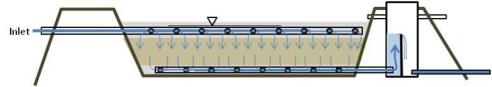
Figure 4-9. Section view of influent-effluent control systems.
Source: Dr. Mark Fitch, Missouri University of Science and Technology.
Screens should be included in the outlet piping to prevent entry of rats or larger animals. When accessing such a structure, be aware that snakes, spiders, and wasps find these structures to be excellent homesteads. Be alert for these animals and take appropriate precautions. Also be aware of the potential for H₂S gas in confined spaces.
4.4.2.5 Pipes and Cleanouts
The iron in most MIW, when oxidized, forms a dense solid capable of plugging pipes. Other metals, which form sulfides and carbonates, have the same potential to cause fouling. Deposition of solids causing this clogging in pipes can be minimized by maintaining high velocities in the range of 1 m/sec, but such high velocities result in high head losses. A different approach is to allow for deposition by increasing pipe size. Larger diameter pipes extend the duration required between cleaning and initially also minimize head losses in piping, although at a higher capital cost for larger pipes. A more general practice is to avoid the use of pipes when practical and instead use channels or subsurface drains. When pipes are used, minimize pipe run distances
When using piping, cleanouts should be used in piping systems to maintain and control deposition. The cleanouts allow access to piping in order to clean that pipe, and generally are installed at locations where deposits are likely to occur, such as at a tee location instead of an elbow or at the base of a pipe run. Because the BCR generates hydrogen sulfide, cleanout caps may accumulate gas and therefore require breather holes. This condition often occurs in cleanouts used for collection piping in vertical flow BCRs. In addition to simple mechanical access, cleanouts may be provided as a location to inject pressurized water or air to cause scour, or to inject and receive cleaning solutions. In general, pressurized air should be avoided in BCR systems due to the potential for pores to become vapor locked. A more mechanical cleaning option can be to run brushes down pipes or even to use a pipeline inspection gauge (PIG). When using a PIG, the system must be designed to include insertion (launch) and collection (receiver) points along relatively straight runs.
Pipe design must also consider placement. Because plastic pipes are affected by UV and piping on the surface will result in more variable temperatures, piping should be located underground when possible or surface piping should be adequately anchored to prevent movement of pipe due to expansion and contraction. In many locations the frost line depth might be considered sufficient insulation to prevent temperature changes. For underground installation, also consider the mechanical load that may be placed on a pipe. Specification of standards such as American Society of Testing and Materials (ASTM) D2665-11 (for PVC) and C2665-11 (for concrete) may be sufficient, but the designer should also consider the possibility of significant dead and live loads from heavy equipment. Small-diameter pipes meet these specifications readily, but larger diameter piping may require thicker backfill over the pipe.
A final aspect of piping design to consider is material choice. Plastic piping is likely to be used in passive systems because most polymers resist acid (with some nylons and polyurethanes as notable exceptions). Not all plastics are the same in terms of chemical resistance, strength, durability, and other properties. For example, in some early BCR designs, high density polyethylene (HDPE) piping resulted in problems because of a tendency to float due to the low density of polyethylene. The relatively large coefficient of thermal expansion can also be a problem for long HDPEhigh density polyethylene runs.
4.4.3 Stormwater
Because passive treatment systems for MIW largely consist of basins open to precipitation l and often are located in fairly steep terrain, the potential effects of precipitation should be included in the design. Rain and snowmelt is clean compared to the MIW influent, and should be excluded from entering the treatment system if possible to reduce the volume of water to be treated. Runoff control structures (i.e., stormwater diversions) should be built around treatment units (and on top of if covers are used) to divert precipitation from entering the system. In extreme some cases, the design can include construction of stormwater culverts to drain the site. Use a "design storm" for the area, such as the precipitation frequency data maintained by NOAANational Oceanic and Atmospheric Administration or the USDAUnited States Department of Agriculture Natural Resources Conservation Service.
Precipitation entering the open basins may affect the residence time in a unit. For example, suppose a BCR is designed to have a hydraulic load of 0.50 m/d. A 2-year 24-hour rain event might add 5 cm of water to the BCR basin. Assuming flow is controlled by the outlet structure, the loading rate during this 24-hour period increased to 0.55 m/d, and the residence time is about 9% less than expected.
However, rain may also affect the flow rate of the influent MIW. If the mine transports shallow groundwater, the rain event may strongly affect the flow rate of the influent. This additional flow is part of the reason that the design team should collect extensive flow data during the testing and data collection phase of the design.
4.4.4 Bed Clogging
Red mud can quickly foul a porous bed and cause hydraulic failure of a BCR. Although the term "red mud" is generally used in terms of alumina production for a strongly alkaline waste, some of the same components, iron oxyhydroxides and aluminum hydroxides, will form from many MIW sources. These solids form dense particles, which easily settle onto and are intercepted in porous beds, eventually plugging that bed.
Most BCRs are not currently designed for backwashing to remove plugging. The best method to control such clogging of the bed is to either prevent oxide formation or to pretreat the water to remove the oxides. In the former case, the MIW is protected from contact with the atmosphere and minimal alkalinity is introduced. In the latter case, alkalinity may be introduced and aeration is allowed to occur (see Section 2.5 for further information).
4.4.5 Short Circuiting
Early prototype BCRs typically failed after two to five years of operation due to loss of uniform permeability, which led to short circuits, preferential pathways for flow, or plugging of the reactor substrate. Short-circuiting was not the sole reason for some BCR failures, however. Although short-circuiting is likely to occur, certain elements of design can help to minimize this phenomenon. These elements include the shape relative to the flow direction and the homogeneity of the media. Prevention of short circuit or flow through the reactor is favored in systems that are significantly longer (flow pathway) than they are wide. This size aspect is easier to achieve in a vertical flow rather than in a horizontal system. The media should be well-mixed, since variation in material sizes across a media bed will result in variation in hydraulic conductivity, which in turn means decreased residence time through those areas with higher hydraulic conductivity.
High loading rates tend to exacerbate short-circuiting. High hydraulic loading results in increased velocities in existing pore spaces, and thus increased scour of the pore walls, which can then increase the pore size. In addition to scour effects, high contaminant loading can affect short-circuiting. As reported in Section 4.4.2.2, if one portion of the substrate has a higher hydraulic conductivity that others, more water will flow through this location thus increasing shear and reaction with the substrate, potentially clearing (and scouring) pores and creating a piping affect. Tortuous, low-velocity pores are prone to clogging by deposition and interception, which decreases the flow through these pores and causes higher flow rates through more open channels. Thus increased precipitate formation may result in short circuiting before clogging a bed in some cases. Corrective measures for short-circuiting may require removal of the BCR contents and rebuilding.
MIW is a challenging fluid for several conventional construction materials. Acid attacks and oxidizes most commonly used metals except perhaps for brass. Also most MIW has a significant concentration of sulfate which in concrete causes surface cracking and expansion, possibly resulting in long-term failure. Engineers should consider other potential problems, for example sulfide generated in reducing conditions plates onto metal surfaces (including 316 stainless steel) and can foul impellers. Polyurethane pumps are not prone to the sulfide plating problem; however, these pumps can be attacked by the reducing conditions and sulfide generation in addition to the acidity. On the other hand, many polymers are resistant to components of MIW, and metals and concretes can be treated to resist chemicals in MIW. The characteristics of the MIW should be checked against the properties of the planned materials.
In almost every case, the basins comprising the treatment system must isolate the water undergoing treatment from groundwater. Section 7 illustrate some of the technical regulatory challenges for the creation of passive treatment systems. One challenge is that the treatment system, even if built on mine tailings, may be considered a wastewater treatment system and thus must have impermeable containment.
Other components of the treatment system that should be protected from potential corrosive conditions from acidic MIW include the protection of influent and effluent structures and an instrumentation monitoring system. Influent and effluent structures should also be resistant to acid attack. Electronics should be protected from MIW, and if inside a building, electronics should be placed within a sealed enclosure and wiring should be placed in conduit piping to minimize contact with any sulfide gas. This separation can be accomplished by placing electronics in a separate space, possibly vented, with communication of wires through a conduit, which is then filled with a sealant. Specify that any interior components must have good resistance to weak (5 – 10%) sulfuric acid solutions. Although the effluent should not be as corrosive as the influent, apply similar considerations for any instrumentation required at the effluent.
4.5 Site Control Design
The BCR design should incorporate elements that minimize the potential impact of visitors. Such impact minimization has two components: hiding the structure and restricting access. If the BCR does not look interesting, it will attract r fewer visitors. For example the system shown in Figure 1-1 appears to be odd farm ponds, with little evidence of technology. People are less likely to visit such a system than one with more evidence of technology or structures. One effective method to minimize the appearance of a BCR is to design a subsurface feed into a gravel or organic (for instance, wood chip) layer so that the surface layer is all that is visible.
In addition to minimizing interest for people, also minimize the site's interest to animals. Many animals are attracted to open and running water. Covering basins such as aerobic polishing cells is generally not practical, but fencing may help to prevent entry. When the BCR system includes active components such as pumps or chemical feed, additional precautions are both advisable and required.
Access to a site is generally restricted by fencing, placing a locked gate on the access road, and placement of clear signage. In conjunction with minimal visibility, these site controls are likely to be more effective if they are low-key. Signage can prohibit trespassing but also, at the access gate, describe the project and provide emergency contacts as mentioned in Section 6.2.1.
Consider a variety of alarms to notify operation and maintenance personnel. In remote or inaccessible locations, it may be wise to duplicate alarm function to avoid unnecessary travel. Examples of alarms are: low or high water level, power loss, temperature exceedances (such as for motors) and intrusion, as well as status or alarm signals provided by any system component with a PLCprogrammable logic controller or similar control. Alarms are generally delivered by an auto dialer, and newer auto dialer systems are able to deliver e-mail and text messages in addition to phone calls.
4.6 Submittals
Submittals play a critical role in construction projects and are typically required for commercial or publically funded projects. The submittal process provides protection for owners in assuring that the plans and specifications are clearly understood by Contractors building the project and determine how the Contractor intends to execute project requirements. The purpose of the submittal process is to ensure quality, functionality and compliance with the plans and specifications prepared by the designer/engineer. In general, the purpose of submittals is to:
- Identify products selected from acceptable products in material specifications.
- Detail how items are constructed and interface with adjacent construction.
- Identify optional characteristics.
- Schedule types of products by location.
- Describe physical and performance criteria.
- Certify that products meet or exceed specified requirements
As part of the process, a Contractor is required to submit a contract submittal list at the beginning of the project. This should include all the submittals that are identified in the specifications.
The primary responsibility for scheduling, management adequacy, accuracy and control of submittals lies with the Contractor doing the work. It is important to note that approved submittals become contract documents. Therefore, the Contractor must understand that the handling of submittals is as important as the actual construction and installation activities. The construction Contractor is responsible for obtaining materials and equipment as specified in the contract.
There are three basic categories of submittals:
- Preconstruction submittals
- Construction submittals
- Closeout submittals
4.6.1 Preconstruction Submittals
Preconstruction submittals are processed prior to start of construction and could include such items as:
- design basis report (bench and pilot study results)
- engineer's design report
- 30% design
- 90% design
- final design plans and specifications
- insurance certificates
- payment and performance bonds
- subcontractor and products lists
- construction schedule
- federal, state and local permits (see http://cfpub.epa.gov/npdes/indpermitting/mining.cfm)
- submittals schedule
- schedule of values
- erosion and stormwater control
- environmental protection, health and safety, construction quality assurance, pollution, and traffic control plans
Each owner may have different requirements for the different preconstruction submittals. For example, payment and performance bonds may not be necessary for small projects and could be waived. Traffic control plans may not be required for remote locations with little traffic, but would be required at sites with significant equipment and vehicle/truck traffic such as at active mining sites.
4.6.2 Construction Submittals
Construction submittals are processed during construction and could include such items as:
- shop drawings
- coordination drawings
- product data
- samples
- quality assurance/quality control (QA/QC) submittals
- informational submittals
- construction photographs
- sustainable design submittals
- payment applications
The type and amount of construction submittals will vary based on the project and documentation requirements. The Contractor is typically required by the contract documents to submit shop drawings, product data, and samples for certain parts of the work. Per the American Institute of Architects, “shop drawings are drawings, diagrams, schedules and other data specially prepared for the Work by the Contractor or a Subcontractor, Sub-subcontractor, manufacturer, supplier or distributor to illustrate some portion of the Work.” The owner’s representative is typically required to review and approve or take other appropriate action upon the receipt of the Contractor’s submittals such as shop drawings.
The principal reason engineers review shop drawings is to evaluate whether the contractor understands the engineering design concepts and to correct any misinterpretations before they are constructed. If the shop drawings indicate that the work depicted will not comply with the intent of the contract drawings and specifications, the engineer has an opportunity to notify the Contractor before the costs of fabrication, purchase, or installation have been incurred. The costly and wasteful alternative to this procedure would be simply to wait until the work has been constructed, inspect it and then either approve or reject it. It is much more economical to review and correct the shop drawings than to remove and replace erroneous construction.
4.6.3 Closeout Submittals
Closeout submittals are processed as part of project closeout and could include such items as:
- written notice of substantial/final completion
- as-built drawings
- final application for payment
- record documents
- O&M data and manuals
- spare parts and extra stock materials
- certificate of payment
- release of liens and waiver of debts and claims
- consent of surety to final payment
- special warranties/Warranty Management Plan
- keying
- sustainable design submittals
As with the construction submittals, the type and amount of closeout submittals will vary based on the project and documentation requirements of the Owner. Typically as-built drawings are required to provide documentation of what was actually constructed and provides the owner with a permanent record of each project feature.
Operation and maintenance data manuals is a critical closeout submittal and includes such items as operating instructions, safety precautions, preventative maintenance, troubleshooting guides, spare parts and supply lists, and warranty information.
Publication Date: November 2013